 |
Firmware (HEX) file and BASIC source code for the Micromite-based Radio IF Alignment [DDSIFAlign.HEX]
Firmware (both with and without pre-loaded BASIC code) and BASIC source for the Touchscreen-based Radio IF Alignment unit with DDS.
The download includes the HEX file with everything included plus the separate BASIC source code.
Also included is the modified version of the code, to allow separate IF alignment input and trigger output pins.
|
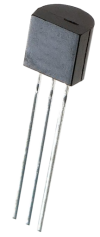 |
MCP1700 3.3V LDO (TO-92)
A 3.3V low-dropout regulator in TO-92 package (MCP1700-3302E/TO).
|
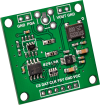 |
AD9833 DDS module with programmable attenuator
A Direct Digital Synthesis module using the AD9833 IC and a 25MHz crystal oscillator. As described in the El Cheapo Asian Electronics Modules article in the April 2017 issue.
This is the version with the onboard programmable gain amplifier.
The SMA and header connectors may be supplied pre-soldered.
|
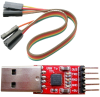 |
CP2102-based USB/TTL serial converter with 5-pin header and 30cm jumper cable
A small USB/serial converter module which plugs straight into a USB port and provides a standard 5-pin header interface with 5V, 3.3V, GND and TTL (3.3V) serial TX/RX pins. Suitable for direct connection to any of the Maximite or Micromite projects.
Modern operating systems like Windows 10 should not require any drivers to use this device - plug it in and it should be recognised and ready to use straight away.
The 5-way cable supplied has female "Dupont" headers on both ends, which plug into standard pin headers. It can be used to connect the adaptor to a Micromite LCD BackPack.
We have only tested this adaptor in Windows; it should work with Linux and Mac OSX.
|
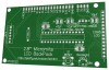 |
Micromite LCD BackPack PCB [2.8-inch version) [07102122]
PCB for the 2.8-inch version of the Micromite LCD BackPack.
Double-sided PCB with plated through holes, solder mask and silkscreen overlay.
86 x 49.5mm.
|
 |
PIC32MX170F256B-50I/SP programmed for the Micromite-based radio IF alignment with DDS [DDSIFAlign.HEX]
A 32-bit PIC microcontroller in 28-pin DIP programmed for the Radio IF Alignment with DDS project. This includes the Micromite software v5.03 as well as the TFT LCD configuration, with the IF Alignment BASIC program pre-loaded.
|
 |
Micromite LCD BackPack PCB patterns (PDF download) [07102121/2]
PDF with the PCB designs for the Micromite LCD BackPack (double-sided).
PCB patterns for both the 2.4-inch (07102121) and 2.8-inch (07102122) versions are included in the one file. Both layers of each PCB are in a single PDF.
Note that this would be impractical to etch yourself and is mainly provided as a reference.
|
 |
Micromite LCD BackPack/Ultrasonic sensor lid cutting diagrams (download)
Cutting diagrams in various file formats (CDR, DXF and PDF) for the Micromite LCD BackPack lid as well as the Ultrasonic Parking Assiistant sensor lid.
|
 |
Matte/Gloss Black UB3 Lid for 2.8-inch Micromite LCD BackPack
A lid laser cut from 3mm black acrylic which replaces the lid supplied with a UB3 "Jiffy" box. Attaches with the supplied screws. One side is gloss black, the other side is matte black. You can fit it either way around.
The 2.8-inch Micromite LCD BackPack is mounted on the rear of the lid using four M3 machine screws, with the touch-screen flush with the top surface. The cut-out is sized to leave minimal clearance around the screen. The cut-out and mounting holes are positioned so that the viewable area of the TFT display is centred. This lid can also be used with the Micromite Plus LCD BackPack.
130.5 x 68.2mm.
Note: for the lid to fit, the LCD pin header solder joints (top side) must be trimmed. Use two M3 washers (or one 1mm thick Nylon washer) as spacers between the TFT PCB and the lid.
|
 |
Clear UB3 Lid for 2.8-inch Micromite LCD BackPack
A lid laser cut from 3mm clear acrylic which replaces the lid supplied with a UB3 "Jiffy" box. Attaches with the supplied screws.
The 2.8-inch Micromite LCD BackPack is mounted on the rear of the lid using four M3 machine screws, with the touch-screen flush with the top surface. The cut-out is sized to leave minimal clearance around the screen. The cut-out and mounting holes are positioned so that the viewable area of the TFT display is centred. This lid can also be used with the Micromite Plus LCD BackPack.
130.5 x 68.2mm.
Note: for the lid to fit, the LCD pin header solder joints (top side) must be trimmed. Use two M3 washers (or one 1mm thick Nylon washer) as spacers between the TFT PCB and the lid.
|
|
Gloss Black UB3 Lid for 2.8-inch Micromite LCD BackPack
A lid laser cut from 3mm gloss black acrylic which replaces the lid supplied with a UB3 "Jiffy" box. Attaches with the supplied screws.
The 2.8-inch Micromite LCD BackPack is mounted on the rear of the lid using four M3 machine screws, with the touch-screen flush with the top surface. The cut-out is sized to leave minimal clearance around the screen. The cut-out and mounting holes are positioned so that the viewable area of the TFT display is centred. This lid can also be used with the Micromite Plus LCD BackPack.
130.5 x 68.2mm.
Note: for the lid to fit, the LCD pin header solder joints (top side) must be trimmed. Use two M3 washers (or one 1mm thick Nylon washer) as spacers between the TFT PCB and the lid.
|
 |
Micromite LCD BackPack V2 complete kit
A kit of all the parts required to build the revised version of the Micromite LCD BackPack. See the parts list link below for details on what is included.
PLEASE NOTE: the 10µF capacitors supplied are either non-polarised SMD or through-hole ceramic types. They have no markings and can be installed either way around.
The PCBs, programmed microcontrollers and regulator are also available separately. For assembly instructions, see the article in the May 2017 issue.
| Programmed with: |
| Cat No SC4237. Price: AUD $70.00 1 |
Log in to purchase |
In stock:  yes (15 available). Estimated dispatch time: 3-10 days yes (15 available). Estimated dispatch time: 3-10 days | | Related to:
|
| View 54 other items relevant to the same project(s) |
| Show kit parts list |
|