 |
Software for the Microbridge
The supplied ZIP file includes pic32prog.exe, the BASIC software to program a PIC for the Microbridge using a Micromite, plus the Microbridge HEX file.
|
|
Firmware (HEX) file and documents for the Micromite Mk.2 and Micromite Plus
Firmware, user manuals, change log and sample C functions for the Micromite Mk.2 and Micromite Plus (v5.05.05).
The regular Micromite HEX file will work on the 28-pin DIP package chip (PIC32MX170F256B) and the 44-pin SMD chip (PIC32MX170F256D).
It's also suitable for the MicroMite LCD BackPack including V2 and V3. See the articles in the January 2015, February 2016 and August 2019 issues for more details.
The Micromite Plus HEX file will work on the 64-pin and 100-pin TQFP package chips (PIC32MX470F512H/L).
[Updated 03/09/2024]
|
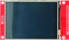 |
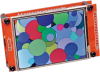
2.8-inch TFT Touchscreen LCD module with SD card socket
A touch screen display module as used in the Micromite LCD BackPack. Uses a 14-pin header for interfacing to the display (ILI9341 controller) and touch sensor, plus a 4 pin (unpopulated) header for the onboard SD card holder.
|
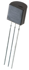 |
MCP1700 3.3V LDO (TO-92)
A 3.3V low-dropout regulator in TO-92 package (MCP1700-3302E/TO).
|
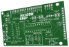 |
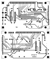
Micromite LCD BackPack V2 PCB [07104171]
PCB of the Micromite LCD BackPack V2.
Double-sided PCB with plated through holes, solder mask and silkscreen overlay.
86 x 50mm.
|
 |
PIC16F1455-I/P programmed for the Microbridge [2410417A.HEX]
A PIC16F1455-I/P 8-bit microcontroller programmed with the firmware for the Microbridge (2410417A.HEX).
|
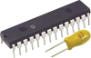 |
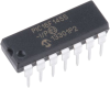
PIC32MX170F256B-50I/SP programmed for the Micromite Mk2 plus capacitor
A 32-bit PIC microcontroller in 28-pin DIP programmed as the Micromite Mk2. Also includes a through-hole Tantalum capacitor to use for its internal regulator - with sufficient capacitance and voltage rating for the job, adn batch tested to have suitably low ESR.
Chips are now programmed with the revised v5.05.03 software (or higher). Note that the capacitor supplied may be a Kemet Solid Molded Tantalum type, in which case the positive lead is indicated by the rounded edge on the case and a dot marking on the top.
|
 |
Micromite LCD BackPack V2 PCB pattern (PDF download) [07104171]
PDF with the PCB design for the revised Micromite LCD BackPack (double-sided).
Both layers are in a single PDF.
|
 |
Matte/Gloss Black UB3 Lid for 2.8-inch Micromite LCD BackPack
A lid laser cut from 3mm black acrylic which replaces the lid supplied with a UB3 "Jiffy" box. Attaches with the supplied screws. One side is gloss black, the other side is matte black. You can fit it either way around.
The 2.8-inch Micromite LCD BackPack is mounted on the rear of the lid using four M3 machine screws, with the touch-screen flush with the top surface. The cut-out is sized to leave minimal clearance around the screen. The cut-out and mounting holes are positioned so that the viewable area of the TFT display is centred. This lid can also be used with the Micromite Plus LCD BackPack.
130.5 x 68.2mm.
Note: for the lid to fit, the LCD pin header solder joints (top side) must be trimmed. Use two M3 washers (or one 1mm thick Nylon washer) as spacers between the TFT PCB and the lid.
|
 |
Clear UB3 Lid for 2.8-inch Micromite LCD BackPack
A lid laser cut from 3mm clear acrylic which replaces the lid supplied with a UB3 "Jiffy" box. Attaches with the supplied screws.
The 2.8-inch Micromite LCD BackPack is mounted on the rear of the lid using four M3 machine screws, with the touch-screen flush with the top surface. The cut-out is sized to leave minimal clearance around the screen. The cut-out and mounting holes are positioned so that the viewable area of the TFT display is centred. This lid can also be used with the Micromite Plus LCD BackPack.
130.5 x 68.2mm.
Note: for the lid to fit, the LCD pin header solder joints (top side) must be trimmed. Use two M3 washers (or one 1mm thick Nylon washer) as spacers between the TFT PCB and the lid.
|
|
Gloss Black UB3 Lid for 2.8-inch Micromite LCD BackPack
A lid laser cut from 3mm gloss black acrylic which replaces the lid supplied with a UB3 "Jiffy" box. Attaches with the supplied screws.
The 2.8-inch Micromite LCD BackPack is mounted on the rear of the lid using four M3 machine screws, with the touch-screen flush with the top surface. The cut-out is sized to leave minimal clearance around the screen. The cut-out and mounting holes are positioned so that the viewable area of the TFT display is centred. This lid can also be used with the Micromite Plus LCD BackPack.
130.5 x 68.2mm.
Note: for the lid to fit, the LCD pin header solder joints (top side) must be trimmed. Use two M3 washers (or one 1mm thick Nylon washer) as spacers between the TFT PCB and the lid.
|
 |
Micromite LCD BackPack V2 complete kit
A kit of all the parts required to build the revised version of the Micromite LCD BackPack. See the parts list link below for details on what is included.
PLEASE NOTE: the 10µF capacitors supplied are either non-polarised SMD or through-hole ceramic types. They have no markings and can be installed either way around.
The PCBs, programmed microcontrollers and regulator are also available separately. For assembly instructions, see the article in the May 2017 issue.
| Programmed with: Lid colour: |
| Cat No SC4237. Price: AUD $70.00 1 |
 |
Add to trolley (available until stock is exhausted) |
In stock:  yes (13 available). Estimated dispatch time: 1-3 days yes (13 available). Estimated dispatch time: 1-3 days | | Related to:
|
| View 48 other items relevant to the same project(s) |
| Show kit parts list |
|