 |
PicoSDR Receiver software
The Pico firmware (.uf2 files) and 3D printing STL files for the PicoSDR Shortwave Receiver.
|
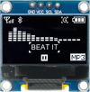 |
0.96in white OLED with SSD1306 controller
A 4-pin (I²C) OLED screen in white. The display active area is approximately 22 x 11mm while the whole module is about 27 x 19mm.
|
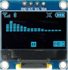 |
0.96in cyan OLED with SSD1306 controller
A 4-pin (I²C) OLED screen in cyan. The display active area is approximately 22 x 11mm while the whole module is about 27 x 19mm.
|
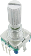 |
Pulse-type rotary encoder with pushbutton and 18t spline shaft
A five-pin rotary encoder with two mounting tabs that has been confirmed as the pulse type. Suitable for use in several projects published in the magazine (see below).
|
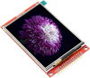 |
3.5-inch TFT Touchscreen LCD module with SD card socket
A 3.5in 480x320 pixel colour touchscreen display module with an ILI9488-compatible controller, as used in the Micromite LCD BackPack V3 and described in the May 2019 issue.
Uses a 14-pin header for interfacing to the display and touch sensor, plus a 4 pin (unpopulated) header for the onboard SD card holder.
|
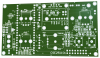 |
PicoSDR Control PCB [CSE251101]
The Control PCB for the PicoSDR project.
Double-sided PCB with plated through holes, green solder mask and white silkscreen overlay.
96.5 x 53.5mm.
|
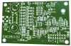 |
PicoSDR RF PCB [CSE251102]
The RF PCB for the PicoSDR project.
Double-sided PCB with plated through holes, green solder mask and white silkscreen overlay.
82.5 x 53mm.
|
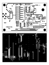 |
PicoSDR PCB patterns [CSE251101-2]
PDFs with the PCB patterns for the PicoSDR.
Both boards are double-sided designs and both layers of each are in individual PDFs.
|
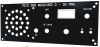 |
PicoSDR front panel (black) [CSE251103]
The front panel for the PicoSDR, made from PCB material. It's black with white text and it has the cut-outs and holes pre-made.
159 x 64.5mm.
|