 |
DCC Booster/Reverse Loop Controller firmware [0911124D.HEX]
The PIC16F18146 firmware package for the DCC Booster/Reverse Loop Controller project (0911124D.HEX).
|
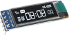 |
0.91-inch white OLED with 4-pin I²C interface
A 128x32 pixels, 0.91-inch white OLED screen as used in the USB-C Power Monitor project.
|
 |
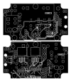
DCC Booster PCB [09111248]
The PCB for the DCC Booster/Reverse Loop Controller.
It's double-sided PCB with plated through holes, green solder mask and white silkscreen overlay.
45 x 79mm.
|
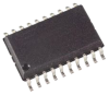 |
PIC16F18146-I/SO programmed for the DCC Booster [0911124D.HEX]
A PIC16F18146-I/SO 8-bit wide SOIC microcontroller programmed with the firmware for the DCC Booster (0911124D.HEX).
|
 |
DCC Booster/Reverse Loop Controller PCB pattern (PDF download) [09111248]
A PDF with the PCB pattern for the DCC Booster/Reverse Loop Controller.
It's a double-sided design and both layers are in a single PDF.
|
 |
DCC Booster front panel (black) [09111249]
The front panel/lid for the DCC Booster/Reverse Loop Controller. It's black, made from PCB material and comes with all the required cut-outs and labels.
83 x 53mm, 0.8mm thick.
|
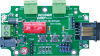 |
DCC Booster/Reverse Loop Controller short-form kit
A partial kit to build the DCC Booster/Reverse Loop Controller. It includes the PCB and all onboard parts except for the optional OLED screen, which is available separately (link below).
If building it into a case, you will also need to source a case, plus the power supply. Otherwise, the kit contains pretty much everything you need. The Pico 2 module is supplied but needs programming.
Photo shows assembled kit. See the link immediately below for a complete list of parts.
|