 |
Basic RF Signal Generator firmware
The ATmega328 firmware for the AD9834-based RF Signal Generator, including both the BASCOM source code and the HEX file.
This updated version (v4.2) provides a more accurate battery voltage display than v4.1.
See the text file in the ZIP for information on how to correctly set the fuses so the firmware will work.
|
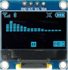 |
0.96in cyan OLED with SSD1306 controller
A 4-pin (I²C) OLED screen in cyan. The display active area is approximately 22 x 11mm while the whole module is about 27 x 19mm.
|
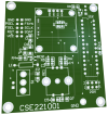 |
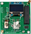
Basic RF Signal Generator main PCB (CSE221001)
The PCB for the AD9834-based RF Signal Generator.
Double-sided PCB with plated through holes, green solder mask and silkscreen overlay.
59 × 65mm
|
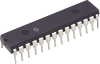 |
ATmega328P programmed with the firmware for the Low-Cost RF Signal Generator [CSE22100A.HEX]
An ATmega328 8-bit microcontroller programmed with the firmware for the AD9834-based RF Signal Generator (CSE22100A.HEX).
Note that this microcontroller is also available as part of the short-form kit for that project.
|
 |
Basic RF Signal Generator PCB pattern (PDF download) [CSE221001]
A PDF with the PCB pattern for the AD9834-based DDS RF Signal Generator. It's a double-sided design and both layers are side-by-side on the same page of the PDF.
|
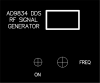 |
Basic RF Signal Generator front panel artwork (PDF download)
A PDF with the front panel artwork for the AD9834-based RF Signal Generator.
|
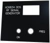 |
Basic RF Signal Generator front panel PCB (CSE220902B)
The front panel for the AD9834-based RF Signal Generator.
It is made from a 77.5 × 64mm PCB, 1mm thick, with a black solder mask.
|
 |
Basic RF Signal Generator short-form kit
A mostly-complete kit for the AD9834-based RF Signal Generator. Click the link below to see what's included in the kit.
Besides this kit, you just need the case, the AA cells and the optional output level adjustment pot (if you plan to fit it).
Note: the photo shows the assembled board. Some parts may have a different appearance than those shown.
|