 |
Firmware and BASIC source code for the 0-110dB RF Attenuator [Attenuator 3]
The ATmega328 microcontroller firmware (HEX file) plus BASIC source code for the 0-110dB RF Attenuator.
If programming the chip with the HEX file yourself, make sure you read the README.TXT file and follow the instructions regarding 'fuse' bits programming.
|
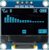 |
0.96in cyan OLED with SSD1306 controller
A 4-pin (I²C) OLED screen in cyan. The display active area is approximately 22 x 11mm while the whole module is about 27 x 19mm.
|
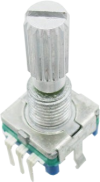 |
Pulse-type rotary encoder with pushbutton and 18t spline shaft
A five-pin rotary encoder with two mounting tabs that has been confirmed as the pulse type. Suitable for use in several projects published in the magazine (see below).
|
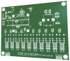 |
0-110dB RF Attenuator PCB [CSE211003]
The PCB for the 110dB RF Attenuator. Also available as part of the kit.
Double-sided PCB with plated through holes, solder mask and silkscreen overlay.
76 x 95.5mm.
|
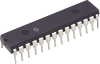 |
ATmega328P programmed with the firmware for the 110dB RF Attenuator [CSE211003.HEX]
An ATmega328 8-bit microcontroller programmed with the firmware for the 110dB RF Attenuator for Signal Generators (CSE211003.HEX).
|
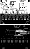 |
0-110dB RF Attenuator PCB pattern (PDF download) [CSE211003A]
A PDF with the PCB design for the 0-110DB Attenuator (double-sided).
Both layers are in a single PDF.
|
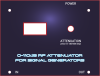 |
Front panel label and drilling diagram for the 110dB RF Attenuator
PDF downloads for the front panel label and drilling diagram for the 110dB RF Attenuator for Signal Generators.
|
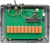 |
Short-form kit for the 0-110dB RF Attenuator
A kit for the 0-110dB Attenuator which includes the PCB, programmed microcontroller and all the other components that mount on the PCB.
All you need to add is the case, panel label, power supply, chassis-mounting DC socket(s), chassis-mounting power switch and the off-board wiring.
Note: photo shows the assembled PCB mounted in the case with off-board components that are not included in the kit.
|