 |
Firmware for the AM/FM DDS Signal Generator [CSE21100A.HEX]
The BASIC source code and HEX file for the ATmega644P in the AM/FM DDS Signal Generator.
Update 04/05/2022: added a text file to the download package with the values that need to be programmed into the three fuse bytes for the firmware to function correctly.
|
 |
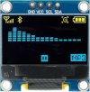
0.96in cyan OLED with SSD1306 controller
A 4-pin (I²C) OLED screen in cyan. The display active area is approximately 22 x 11mm while the whole module is about 27 x 19mm.
|
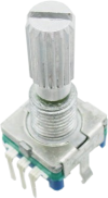 |
Pulse-type rotary encoder with pushbutton and 18t spline shaft
A five-pin rotary encoder with two mounting tabs that has been confirmed as the pulse type. Suitable for use in several projects published in the magazine (see below).
|
 |
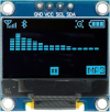
0.96in yellow/cyan OLED with SSD1306 controller
A 4-pin (I²C) OLED screen with the top quarter in yellow and the rest in cyan. The display active area is approximately 22 x 11mm while the whole module is about 27 x 19mm.
|
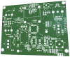 |
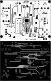
AM/FM DDS Signal Generator PCB [CSE211002]
The PCB for the AM/FM/DDS Signal Generator.
Double-sided PCB with plated through holes, solder mask and silkscreen overlay.
100 x 78.5mm.
|
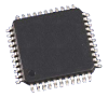 |
ATMEGA644PA-AN programmed for the AM/FM DDS Signal Generator [CSE21100A.HEX]
An ATMEGA644PA-AN 8-bit, 20MHz processor in a 44-pin TQFP package, programmed with the software for the AM/FM DDS Signal Generator.
|
 |
AM/FM DDS Signal Generator PCB pattern (PDF download) [CSE211002]
A PDF with the PCB design for the AM/FM DDS Signal Generator (double-sided).
Both layers are in a single PDF.
|
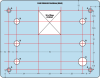 |
Front panel label and drilling diagram for the AM/FM DDS Signal Generator
PDF downloads for the front panel label and drilling diagram for the AM/FM DDS Signal Generator.
There are two drilling diagrams: one for mounting the PCB in the the base of the case (as recommended), and another for mounting it on the inside of the lid.
|