 |
Buck/Boost Charger Adaptor software & laser cutting files (1410822A.HEX)
The firmware (1410822A.HEX), C source code, MPLAB X project and laser cutting files (.dxf, .scad) for the Multi-Stage Buck-Boost Charger Adaptor project.
|
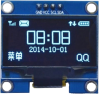 |
1.3-inch blue OLED with 4-pin I²C interface
128x64 pixel, 3cm OLED display to suit the June 2019 GPS Speedo/Clock/Volume Control project.
|
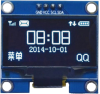 |
1.3-inch white OLED with 4-pin I²C interface
128x64 pixel, 3cm OLED display to suit the June 2019 GPS Speedo/Clock/Volume Control project.
|
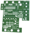 |
Buck/Boost Charger Adaptor PCB [14108221]
The PCB for the Multi-Stage Buck-Boost Charger Adaptor.
Double-sided PCB with plated through holes, solder mask and silkscreen overlay.
75 x 80mm.
|
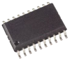 |
PIC16F1459-I/SO programmed for the Buck/Boost Battery Charger Adaptor (1410822A.HEX)
A PIC16F1459-I/SO 8-bit SMD microcontroller programmed with the firmware for the Buck-Boost Charge Adaptor (1410822A.HEX).
|
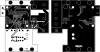 |
Buck/Boost Charger Adaptor PCB pattern (PDF download) (14108221)
A PDFs with the PCB pattern for the Multi-Stage Buck-Boost Charger Adaptor.
Both layers of the PCB are in a single PDF.
|
 |
Laser-cut clear acrylic front panel for Buck/Boost Charge Adaptor
A 75 x 80mm laser-cut piece of 3mm thick clear acrylic that forms a cover for the Multi-Stage Buck-Boost Charger Adaptor. It's also included in the kit we sell for that project.
|
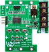 |
Complete kit for the Buck/Boost Charger Adaptor
A kit that includes everything in the parts list for the Multi-Stage Buck-Boost Charger Adaptor except the LED Driver Module (available as a separate kit).
The PCB, laser-cut clear acrylic cover and microcontroller are included. The micro is pre-programmed.
Note: photo shows the assembled kit before the OLED screen is installed.
|
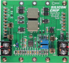 |
Complete kit for the High Power Buck-Boost LED Driver
A kit including the PCB and all the onboard parts to build the High Power Buck/Boost LED Driver.
It includes the four diodes and two inductors needed to build the full-power version.
The kit does not include an LED panel. Those are available separately in two versions (warm white or cool white) - see the links immediately below.
Note: photo shows fully assembled PCB.
|