 |
Firmware and bezel laser cutting files for the USB Cable Tester [0410821A.HEX]
The firmware zip contains the MPLAB X project to build the USB Cable Tester firmware, plus two HEX files, one to suit the PIC16F18877 and one for the PIC16F18875.
A second zip file is included, which contains the .dxf and .scad files defining the laser-cut LCD bezel.
Update 5/11/2021: revised firmware (0410821C-D) has been added. This halves the default scrolling speed of text on the LCD to make it more legible. The original speed was OK with the contrast settings we used on our prototype, but some people might find this slower speed easier to read. It also adds a hidden option 4 to the calibration menu, allowing the scrolling speed to be set in three steps. 1 = original speed, 2 = new slower speed, 4 = even slower. There's no disadvantage to using this version.
|
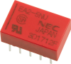 |
Relay - 1A DPDT 5V DC coil (EA2-5NU)
A small EA2-5NU 5V DC relay, as used in various projects.
|
 |
IPP80P03P4L-07 high-current P-channel Mosfet
A high-current P-channel Mosfet with low on-resistance in a standard TO-220 package. Note: package marking is '4P03L07'.
This is a faster switching, lower-cost version of the IPP80P03P4L-04 Mosfet that we also sell, but with slightly higher on-resistance.
Its critical specifications are:
Maximum drain-source voltage: 30V
Maximum gate-source voltage: +5V, -16V
Maximum continuous drain current: 80A
Maximum pulsed drain current: 320A
Maximum dissipation: 88W
Gate threshold voltage: 1-2V
On-resistance: 5.9mΩ
Input capacitance: 4.4nF
Output capacitance: 1.2nF
Reverse transfer capacitance: 30pF
While this is not a complementary type to the IPP80N06S4L-07 N-channel type we also sell, it is very well matched.
|
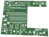 |
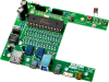
USB Cable Tester main PCB [04108211]
The main PCB for the USB Cable Tester.
Double-sided PCB with plated through holes, solder mask and silkscreen overlay.
130 x 102mm.
Note that this PCB is also available in the USB Cable Tester kit.
|
 |
PIC16F18877-I/P programmed for the USB Cable Tester [0410821C.HEX]
An 8-bit, PIC microcontroller in 40-pin DIP programmed for the USB Cable Tester (0410821C.HEX).
Note that this microcontroller is also available as part of the USB Cable Tester kit.
|
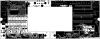 |
USB Cable Tester PCB patterns (PDF download) [04108211/2]
A PDF with the PCB design for the USB Cable Tester (double-sided). Both layers of both boards are in a single PDF.
A second PDF is provided which contains the front panel outlines and labelling.
|
 |
USB Cable Tester front panel PCB [04108212]
The front panel for the USB Cable Tester.
Made as a double-sided PCB with a green solder mask and silkscreen overlay for labelling.
134 x 30mm.
Note that this panel is also available in the USB Cable Tester kit.
|
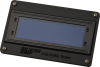 |
Laser-cut acrylic bezel for USB Cable Tester
A laser-cut 103 x 65 x 3mm black acrylic bezel to suit a 20x4 LCD screen, as used in the USB Cable Tester project. Screws & LCD shown in photo not included.
|
 |
Short form kit for the USB Cable Tester
A kit that includes all the parts to build the USB Cable Tester as presented in the magazine, except for the plastic instrument case (available from Altronics & Jaycar; see the article for part numbers).
See the parts list link below for details on what is included.
No AA cells are included. Apart from those and the case, you get everything you need to build a fully working USB Cable Tester.
Note: photo shows assembled PCB without LCD screen or bezel.
|