 |
Modified software for the Micromite Boat Computer
Modified software downloads for the Boat Computer as described in Circuit Notebook, November 2020:
- Version V4G adds a 24hr clock on the heading screen; the baud rate is locked to 9600; it has automatic backlight control; and the speed reading is provided in 0.1km/h resolution.
- Version V7 adds a digital speedometer and compass.
|
|
Firmware (HEX) file and BASIC source code for the Micromite-based Touch-screen Boat Computer with GPS [V7]
Revised firmware (both with and without pre-loaded BASIC code) and BASIC source for the GPS Boat Computer.
Includes Micromite firmware.
Version 7 improvements: Added altitude readout as described in Circuit Notebook, August 2020.
Version 6 improvements: Changed the 'speed' variable to a float to improve Km/h accuracy.
Version 5 improvements: Fixed a small issue related to drawing the blue border which only affects Micromites running MMBasic V5.2. Note that BoatComputerFullV5.hex uses MMBasic V5.1.
Version 4 improvements: Fixed an issue that prevented selecting the SET button for some POIs.
Version 3 improvements: Fixed a bug which could cause the software to repeatedly crash and restart when creating a POI at lat/lon 0,0 (or another distant location).
Version 2 improvements: You can now have over fifty Points of Interest. The heading indicator and POI direction indicator are now suppressed when the boat is stationary. Improved the rendering of the heading needle. Removed the slash from the numeric zero character in one of the fonts. See changelog in ZIP file for more details.
For the Micromite user manual, see the separate shop item.
|
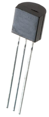 |
MCP1700 3.3V LDO (TO-92)
A 3.3V low-dropout regulator in TO-92 package (MCP1700-3302E/TO).
|
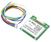 |
VK2828U7G5LF TTL GPS/GLONASS/GALILEO module with antenna and cable
A VK2828U7G5LF GPS module from GMOUSE. Data sheet is available at https://github.com/CainZ/V.KEL-GPS/blob/master/VK2828U7G5LF%20Data%20Sheet%2020150902.pdf
Features onboard ceramic patch antenna. Basic specifications are:
- 28 x 28 x 8.6mm
- 3.3-5V supply at 25-35mA
- TTL signalling, default 9600 baud
- Enable input, 1PPS output plus serial TX & RX with NMEA 0183
- Tracking sensitivity -162dBm, capture sensitivity -160dBm
- Cold start 26 seconds, hot start one second
- 1-10Hz updates
A short 6-way cable with plug is supplied. If you order this, you may receive a VK2828U8G5LF which is an updated version of the module with slightly better specifications but provides the same functions.
| Cat No SC3362. Price: AUD $25.00 1 |
 |
Add to trolley |
In stock:  yes (10 available). Estimated dispatch time: 1-3 days yes (10 available). Estimated dispatch time: 1-3 days | Related to:
- Project: A GPS-Synchronised Clock (March 2009 [print issue] [online issue])
- Project: A GPS-Synchronised Clock (March 2009 [print issue] [online issue])
- Project: Dead-Accurate 6-Digit GPS-Locked Clock, Pt.1 (May 2009 [print issue] [online issue])
- Project: GPS Driver Module For The 6-Digit Clock, Pt.2 (June 2009 [print issue] [online issue])
- Project: GPS Synchronisation For Clocks With Sweep Hands (November 2009 [print issue] [online issue])
- Project: GPS Synchronisation For Clocks With Sweep Hands (November 2009 [print issue] [online issue])
- Project: A Multi-Function GPS Car Computer, Pt.1 (January 2010 [print issue] [online issue])
- Project: A Multi-Function GPS Car Computer, Pt.2 (February 2010 [print issue] [online issue])
- Project: Build A GPS Boat Computer (October 2010 [print issue] [online issue])
- Project: A 2.5GHz 12-digit Frequency Counter, Pt.1 (December 2012 [online issue])
- Project: A 2.5GHz 12-Digit Frequency Counter, Pt.2 (January 2013 [print issue] [online issue])
- Project: Accurate GPS 1pps Timebase For Frequency Counters (February 2013 [online issue])
- Project: Deluxe GPS 1pps Timebase For Frequency Counters (April 2013 [print issue] [online issue])
- Project: Build A GPS Tracker & Record Your Journeys (November 2013 [print issue] [online issue])
- Project: L-o-o-o-n-g Gating Times For The 12-Digit Counter (July 2014 [print issue] [online issue])
- Project: 6-Digit Retro Nixie Clock Mk.2, Pt.1 (February 2015 [print issue] [online issue])
- Project: 6-Digit Retro Nixie Clock Mk.2, Pt.2 (March 2015 [print issue] [online issue])
- Project: High Visibility 6-Digit LED GPS Clock (December 2015 [print issue] [online issue])
- Project: High Visibility 6-Digit LED GPS Clock, Pt.2 (January 2016 [print issue] [online issue])
- Project: Touch-Screen Boat Computer With GPS (April 2016 [print issue] [online issue])
- Project: Touchscreen Super Clock (July 2016 [print issue] [online issue])
- Project: GPS-synchronised Analog Clock Driver (February 2017 [print issue] [online issue])
- Circuit Notebook: Remote water level monitoring using LoRa and Arduino (July 2017 [print issue] [online issue])
- Project: An Arduino Data Logger with GPS (August 2017 [print issue] [online issue])
- Project: Arduino Data Logger Part 2 (September 2017 [print issue] [online issue])
- Feature: El Cheapo Modules Part 10: GPS receivers (October 2017 [print issue] [online issue])
- Project: Super Clock now shows your electricity tariff (July 2018 [print issue] [online issue])
- Project: GPS-synched Frequency Reference Pt.1 (October 2018 [print issue] [online issue])
- Project: GPS-synched, lab-quality frequency reference (Part 2) (November 2018 [print issue] [online issue])
- Project: Very accurate speedo, car clock & auto volume change (June 2019 [print issue] [online issue])
- Project: Advanced GPS Computer - Part 1 (June 2021 [print issue] [online issue])
- Project: Advanced GPS Computer – Part 2 (July 2021 [print issue] [online issue])
- Project: New GPS-Synchronised Analog Clock (September 2022 [print issue] [online issue])
|
| View 119 other items relevant to the same project(s) |
|
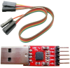 |
CP2102-based USB/TTL serial converter with 5-pin header and 30cm jumper cable
A small USB/serial converter module which plugs straight into a USB port and provides a standard 5-pin header interface with 5V, 3.3V, GND and TTL (3.3V) serial TX/RX pins. Suitable for direct connection to any of the Maximite or Micromite projects.
Modern operating systems like Windows 10 should not require any drivers to use this device - plug it in and it should be recognised and ready to use straight away.
The 5-way cable supplied has female "Dupont" headers on both ends, which plug into standard pin headers. It can be used to connect the adaptor to a Micromite LCD BackPack.
We have only tested this adaptor in Windows; it should work with Linux and Mac OSX.
|
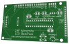 |
Micromite LCD BackPack PCB (2.8-inch version) [07102122]
PCB for the 2.8-inch version of the Micromite LCD BackPack.
Double-sided PCB with plated through holes, solder mask and silkscreen overlay.
86 x 49.5mm.
|
 |
PIC32MX170F256B-50I/SP programmed for the Micromite-based Touch-screen Boat Computer [BoatComputerFullV7.hex]
A 32-bit PIC microcontroller in 28-pin DIP programmed for the GPS Boat Computer. This includes the Micromite software as well as the TFT LCD configuration, with the Boat Computer BASIC program pre-loaded.
Version 7 improvements: Added altitude readout as described in Circuit Notebook, August 2020.
Version 6 improvements: Changed the 'speed' variable to a float to improve Km/h accuracy.
Version 5 improvements: Fixed a small issue related to drawing the blue border which only affects Micromites running MMBasic V5.2. Note that BoatComputerFullV5.hex uses MMBasic V5.1.
Version 4 improvements: Fixed an issue that prevented selecting the SET button for some POIs.
Version 3 improvements: Fixed a bug which could cause the software to repeatedly crash and restart when creating a POI at lat/lon 0,0.
Version 2 improvements: You can now have over fifty Points of Interest. The heading indicator and POI direction indicator are now suppressed when the boat is stationary. Improved the rendering of the heading needle. Removed the slash from the numeric zero character in one of the fonts. See changelog in ZIP file for more details.
|
 |
Micromite LCD BackPack PCB patterns (PDF download) [07102121/2]
PDF with the PCB designs for the Micromite LCD BackPack (double-sided).
PCB patterns for both the 2.4-inch (07102121) and 2.8-inch (07102122) versions are included in the one file. Both layers of each PCB are in a single PDF.
Note that this would be impractical to etch yourself and is mainly provided as a reference.
|
 |
Micromite LCD BackPack/Ultrasonic sensor lid cutting diagrams (download)
Cutting diagrams in various file formats (CDR, DXF and PDF) for the Micromite LCD BackPack lid as well as the Ultrasonic Parking Assiistant sensor lid.
|
 |
Matte/Gloss Black UB3 Lid for 2.8-inch Micromite LCD BackPack
A lid laser cut from 3mm black acrylic which replaces the lid supplied with a UB3 "Jiffy" box. Attaches with the supplied screws. One side is gloss black, the other side is matte black. You can fit it either way around.
The 2.8-inch Micromite LCD BackPack is mounted on the rear of the lid using four M3 machine screws, with the touch-screen flush with the top surface. The cut-out is sized to leave minimal clearance around the screen. The cut-out and mounting holes are positioned so that the viewable area of the TFT display is centred. This lid can also be used with the Micromite Plus LCD BackPack.
130.5 x 68.2mm.
Note: for the lid to fit, the LCD pin header solder joints (top side) must be trimmed. Use two M3 washers (or one 1mm thick Nylon washer) as spacers between the TFT PCB and the lid.
|
 |
Clear UB3 Lid for 2.8-inch Micromite LCD BackPack
A lid laser cut from 3mm clear acrylic which replaces the lid supplied with a UB3 "Jiffy" box. Attaches with the supplied screws.
The 2.8-inch Micromite LCD BackPack is mounted on the rear of the lid using four M3 machine screws, with the touch-screen flush with the top surface. The cut-out is sized to leave minimal clearance around the screen. The cut-out and mounting holes are positioned so that the viewable area of the TFT display is centred. This lid can also be used with the Micromite Plus LCD BackPack.
130.5 x 68.2mm.
Note: for the lid to fit, the LCD pin header solder joints (top side) must be trimmed. Use two M3 washers (or one 1mm thick Nylon washer) as spacers between the TFT PCB and the lid.
|
|
Gloss Black UB3 Lid for 2.8-inch Micromite LCD BackPack
A lid laser cut from 3mm gloss black acrylic which replaces the lid supplied with a UB3 "Jiffy" box. Attaches with the supplied screws.
The 2.8-inch Micromite LCD BackPack is mounted on the rear of the lid using four M3 machine screws, with the touch-screen flush with the top surface. The cut-out is sized to leave minimal clearance around the screen. The cut-out and mounting holes are positioned so that the viewable area of the TFT display is centred. This lid can also be used with the Micromite Plus LCD BackPack.
130.5 x 68.2mm.
Note: for the lid to fit, the LCD pin header solder joints (top side) must be trimmed. Use two M3 washers (or one 1mm thick Nylon washer) as spacers between the TFT PCB and the lid.
|