 |
Firmware (.ino sketches) for the Multi Diode Curve Plotter
This download package contains two Arduino sketches, one which is the main firmware for the Touch Controlled All-diode Checker and Plotter, and one of which is used to calibrate the device.
Both sketches come with a few header (.h) and C++ source (.cpp) files which provide the library functions that they need.
|
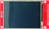 |
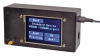
2.8-inch TFT Touchscreen LCD module with SD card socket
A touch screen display module as used in the Micromite LCD BackPack. Uses a 14-pin header for interfacing to the display (ILI9341 controller) and touch sensor, plus a 4 pin (unpopulated) header for the onboard SD card holder.
|
 |
STFU13N65M2 650V logic-level Mosfet
One STFU13N65M2 650V logic-level Mosfet. Suited for high speed switching of rectified mains or other high voltage supplies.
One or two are required for the Hifi Stereo Valve Preamplifier.
Specifications:
Maximum drain-source voltage: 650V
Maximum continuous drain current: 10A
Maximum pulsed drain current: 40A
Maximum on-resistance: 0.43Ω
Gate charge: 17nC
Input capacitance: 590pF
Turn-on delay time: 11ns
Rise time: 7.8ns
Turn-off delay time: 38ns
Fall time: 12ns
This replaces the IPA60R520E6 previously used as it has similar or superior specifications.
|
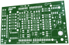 |
Diode Curve Plotter PCB [04112181]
PCB for the Diode Curve Plotter.
Double-sided PCB with plated through holes, solder mask and silkscreen overlay.
99 x 59mm.
|
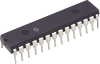 |
PIC32MX170F256B-50I/SP programmed for the Multi Diode Curve Plotter [0411218A.hex]
A 32-bit PIC microcontroller in 28-pin DIP package programmed for the Touch Controlled All-diode Checker and Plotter. This includes the Micromite software as well as the TFT LCD configuration, with the Diode Curve Plotter BASIC program pre-loaded.
|
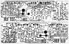 |
Multi Diode Curve Plotter PCB pattern (PDF download) [04112181]
PDF with the PCB design for the Touch Controlled All-diode Checker and Plotter (double-sided).
Both layers are in a single PDF.
|
 |
Multi Diode Curve Plotter box cutting diagram (PDF download)
A PDF with the box cutting details for the All-diode Checker and Plotter.
The second download (ZIP file) includes the lid laser cutting details.
|
 |
Matte Black UB3 Lid for the Multi Diode Curve Plotter
A lid laser cut from 3mm black acrylic which replaces the lid supplied with a UB3 "Jiffy" box. The side facing outwards is matte black.
The Diode Curve Plotter assembly is mounted on the rear of the lid using four M3 machine screws, with the touch-screen flush with the top surface. The cut-out is sized to leave minimal clearance around the screen.
120 x 62mm.
Note: for the lid to fit, the LCD pin header solder joints (top side) must be trimmed. Use two M3 washers (or one 1mm thick Nylon washer) as spacers between the TFT PCB and the lid.
|